Alessandro Rush
Product Design

BAT NEST

This project had a strict timetable of one week from start to completion. Its purpose was to engage the public in following local wildlife. I chose to come up with an updated bat shelter (which I called the Bat Nest) with an internal camera to allow the public to view the bats as they rest. I also created an app concept for the public to watch the bats and to be able to view different information and data collected by the Bat Nest.
Sketches
To start this project I made some sketches based on drawings of already-existing bat shelters. This was to gain a better understanding the necessary product characteristics. The two most commonly-used designs are in flat and box-type shapes.
From here I drew some sketches of the bat shelter, ensuring that they included space for a camera. At this stage I found an issue with box and cylinder- shaped nests in that the central pillar would interrupt the camera view to the other side. For this reason I decided to go for a flat-shaped design.
Finally I produced a more detailed final version of the bat shelter, including the different parts and some of the features that would need to be included.


The Bat Nest has a separate part on the side of the product that can be accessed externally by removing the access panel: this area is where the camera is fitted. The camera has the ability to display the entire shelter via a glass viewing window.
Finally there are indents on the front of the back plate, enabling the bats to climb into the nest and rest in a hanging position.
CAD & Renders
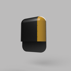
Once the design was chosen a CAD model was made. This design has a curved edge on the top since - being a outdoor product - it needs to be rain-resistant, with a curved roof to allow water to slide off. The back of the model is flat to ensure a clear view of the whole nest in the camera feed. The flat back also allows the Bat Nest to be mounted on both trees and walls.


The model is made up of 4 separate parts:
-Back Grip Plate
-Main Cover Shell
-Access Latch
-Viewing Window
All the parts are put together using screws except for the Viewing Window, which is glued onto the counter edge on the Main Cover Shell.
 Main Cover Shell |  Back Grip Plate |  Viewing Window |
|---|---|---|
 Access Panel |
Parts & Assembly
 |  |  |  |
|---|---|---|---|
 |


Digital Tests
To verify the feasibility of the concept I carried out Digital Tests in SolidWorks on the trickiest part of the model: the Main Cover Shell.


Moldflow Analysis
I assigned the injection point for the Moldflow to the central part of the nest, since this was the position most likely to reach all sides rapidly. The data showed that the mould would fill with ease, as shown in the image below. The model would nonetheless have some air gaps that would need to be removed, since they are in the middle of the plane surfaces.


Fill Time
The fill time for the part is of around 9.3 seconds from the central injection location (as shown in the image). This does not seem excessive given the size of the part.

Volume Shrinkage at end of Fill
Shrinkage seems to be mostly concentrated on the section corresponding to the camera location (this is also the last part to fill).

Temperature at end of fill
The hottest area at end of fill is at the injection point: with a fill time of 9 seconds this makes sense, since this point constantly has material flowing into it. The coolest parts are the points were the screws are located and all the thinner edges, since heat can disperse more easily in proximity to cool air.

Shrink Marks
Shrink marks are mostly concentrated in larger areas. Although the image is mainly red, shrinkage is only 0.05 mm - not enough to make a significant difference.
App
To engage the public in the project I came up with a rough idea for an app that enables people to view the bats inside the Bat Box.
The app has a login feature enabling each individual person to access a personal space on the app. To navigate the app, users simply have to tap on the menu at the bottom and select from the different icons to direct the app to the desired page.


